
Datsun 240Z - Chassis Jig |
www.VORD.net |
Doimensions for the jig are here: 240Z chassis jig
A fair bit of structure will need to be replaced during this project including floors, one sill, underfloor chassis, front chassis, much of the rest of the front structure and, er, the roof. Also the car isn't quite straight so it will need a chassis jig to line things up so the replacement structure ends up in the right place. See the initial inspection for details.
 |
Fortunately I already have a chassis jig (the link is to a page detailing the construction). But it is currently more suited to renovating Renault 4 chassis than Datsuns. It is built around a C section frame, 150mm*100mm and around 10mm thick. It's very heavy. The attachments in the photo mount to the mounting points on the Renault so aren't much use for the Datsun, but the frame itself will be useful for the Datsun. |
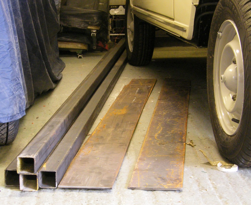 |
Steel prices have more than doubled since I made the jig. Lighter sections are cheaper, so for making attachments to adapt the jig for the Datsun I've gone for 50mm box section (2.5mm wall thickness). The 5mm plate in the photo will be used to make flanges to bolt the box section into position. Incidentally, the car in the photo is the last one to use the jig. See it's restoration. |
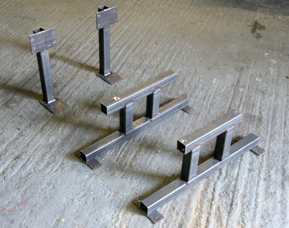 |
I found a 240Z factory workshop manual on the internet which has enough dimensions to build a jig. The first jig attachments to be made will fit the gearbox mounting (foreground), the rear suspension front mounting, and the two front chassis rails. Further attachments will be needed for the front strut tops, the sills, and the rear of the chassis. |
 |
Here's another attachment in progress. It's for the rear of the front longerons. I realised the tunnel mounting wouldn't be the best place to support the weight of the car while replacing the floors. It's possible to achieve good accuracy by drilling the holes first, then setting up before welding using the lines marked for the holes as reference. Welding the parts together on a big flat bench keeps them straight. |
 |
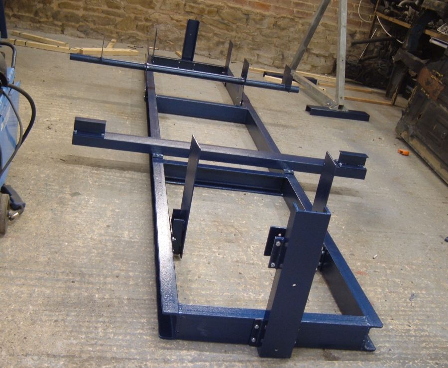
I'm trial fitting the various parts of the jig in the photo, but won't get serious about setting everything up until after I've drilled some mounting holes in the jig frame. Despite being made out of very heavy section the jig can twist and bend, so it will need to be set up straight and level at a good working height, then left in position until the end of the project. |
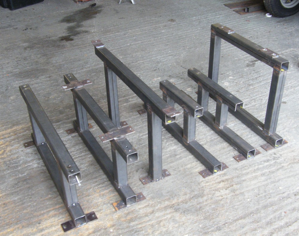 |
The jig sections are multiplying! There is almost a full set in the photo. The heights should be fairly accurate as these was set before welding the sections together. |
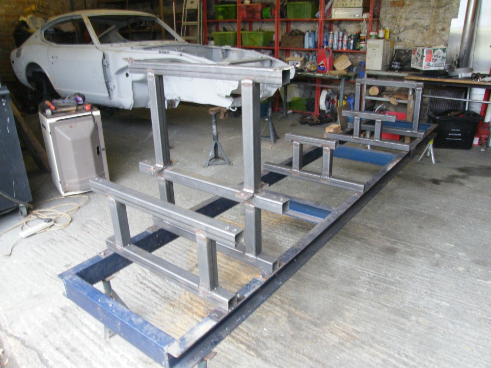 |
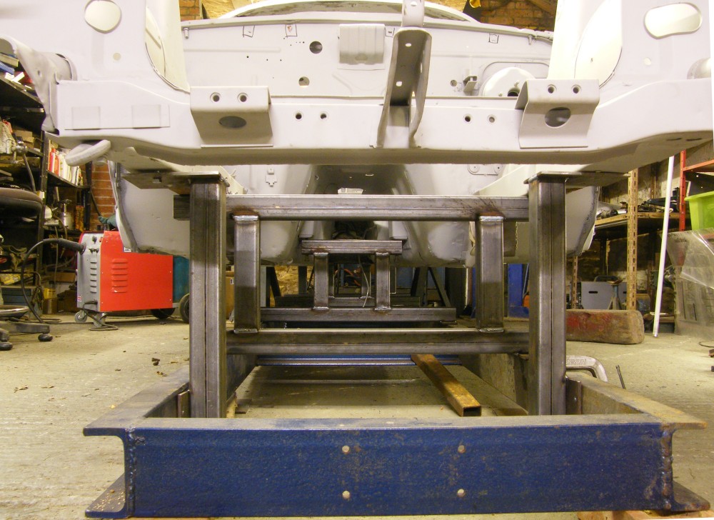
The fore-aft positions of the jig parts were taken from the manual and referenced to the double decker section towards the front of the photo (which will support the strut tops). The sections were positioned side to side by referencing the holes that mount to the car with the edges of the jig frame. I've marked one side of them with yellow paint to make sure none are reversed. My garage floor is squint - it used to be a cow shed and drains towards the door. After mounting the car I leveled the jig with shims on top of the axle stands to ensure there was not any twist in the jig frame. |
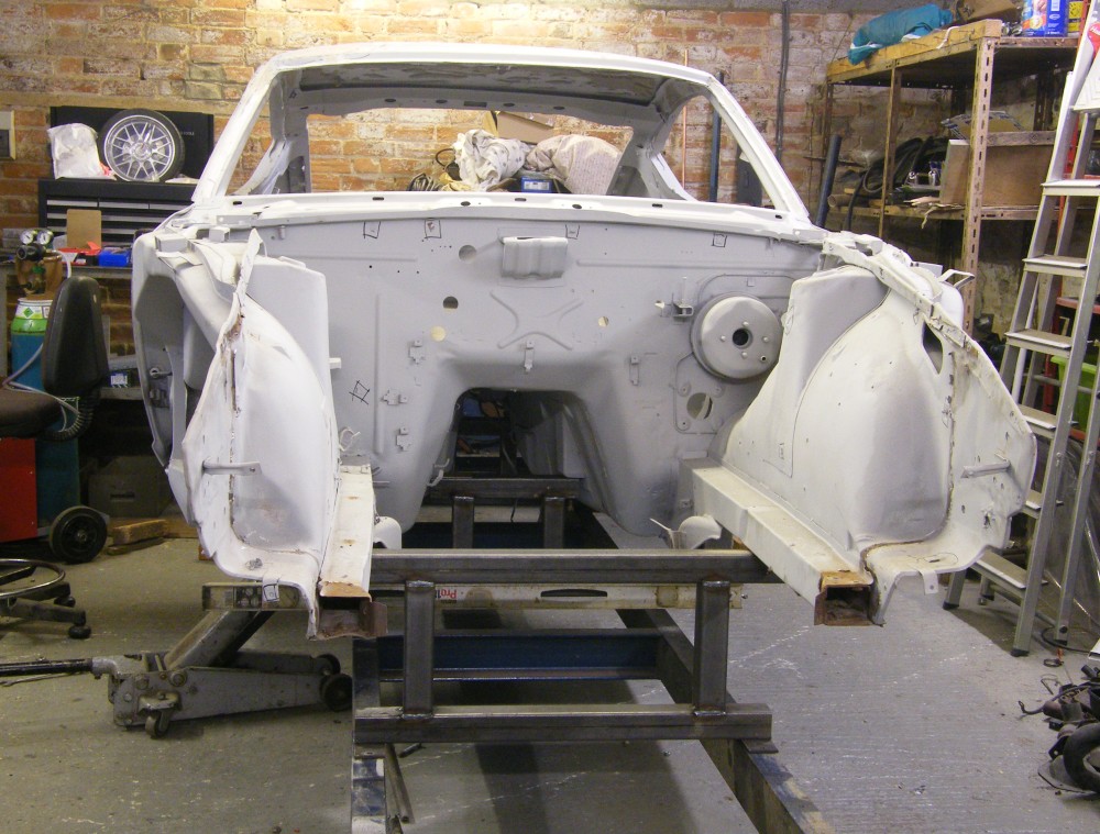 |
While the jig might be accurate and straight the car certainly isn't. Apart from the obvious twist at the front spotted during the initial inspection, there are manufacturing tolerances. The gearbox mounting needed a 2mm shim in order to level up the sills even though there is no evidence of damage to the central tub. With the shim inserted the front and rear of both sills are spot on. The front of the car was twisted, the left side high and the right side low. The left side has been bodged, but the right side looked OK even though it was low. It appears to have been the radiator panel that was holding that side in the wrong position. The front end isn't stiff at all with that panel removed. |
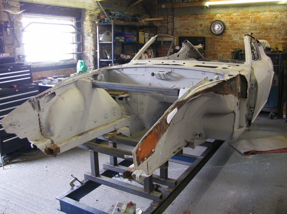 |
A few more body sections needed to be removed to allow the car to sit straight on the jig - just about all of the parts the American bodyman had messed with. Those panels would have had to come off anyway as they were brazed in place. With the suspension mounting points in the right place all that remains is to trial fit the panels and brace the door gaps in the right place. If everything fits I can get on with replacing the bottom half of the shell. |
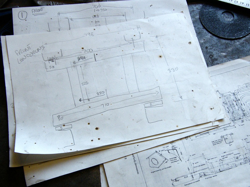 |
2 years after posting pictures of a jig on the internet someone will ask me for the dimensions. By that time I will have mislaid the drawings. This time I've put them in a Datsun 240Z Chassis Jig pdf for you to download. I think the Gearbox mounting lateral direction might be wrong. Should be offset to one side by 10mm from centre and I don't think I corrected that. Also the drawings are not exactly to CAD standard, so it might be you'll have to spend a little time figuring them out. Materials and consumables at 2010 prices were about £120, and the build took me about 25 hours. |
Next > Vord's Classic Cars > Datsun 240Z > Front Chassis